June 18, 2017
Introduction
The main objective for this project was to take a video feed from an onboard camera and identify the lane lines and the curvature of the road. The below image presents an example of one frame of the output that is expected. This projected uses different computer vision techniques to extract the lane lines in the frames. Code for this project can be found in this Jupyter Notebook and the video for this project can be found here.

The goals / steps of this project are the following:
- Compute the camera calibration matrix and distortion coefficients given a set of chessboard images
- Apply a distortion correction to raw images
- Use color transforms, gradients, and sobel filters to create a thresholded binary image
- Apply a perspective transform to rectify binary image ("birds-eye view")
- Detect lane pixels and fit to find the lane boundary
- Determine the curvature of the lane and vehicle position with respect to the center of the lane
- Warp the detected lane boundaries back onto the original image
- Output visual display of the lane boundaries and numerical estimation of lane curvature and vehicle position
Camera Calibration
One of the first steps to the project is to take in the images from the forward facing camera. However, these images typically have some distortion that needs to be accounted for if we want to later be able to calculate the curvature of the lane lines. Specifically, this has to do with the lenses that are in the cameras used to take pictures.
One of the ways to address this distortion is to calibrate our camera if we know how much the lenses distort our image. To start with, we can take a look at a chessboard image (we know how it should actually look with no distortion) before we calibrate and undistort the image. This will allow us to calculate how much distortion is present and correct for it (most of the heavy lifting is done by OpenCV). We can do this same calibration with a set of chessboard images. Below are a couple images without undistortion.

As seen in the above examples, the images are quite varied which allows us to correct for all types of images that the camera will eventually see.
Now, we can start to calibrate the camera. One way of doing this is to map points on the distorted image to an undistorted image (where we know all the location of those points, then we can transform or undistort the original image. In the case of using chessboards, the intersection of the black and white squares is a really good place to start.
We can use the OpenCV package to find these intersection points using the findChessboardCorners function read more here. This will return a set of detected corner coordinates if the status is 1 or no corners if no corners could be found (status of 0).
![alt text]corners_img]
As we can see, the function did a pretty good job of identifying the internal corners in the image of the chessboard. Now we need to undistort the image by using a mapping of these found corners our understanding of how a chessboard usually looks.
First we need to store these points so that we can use the points to undistort our images then we can calibrate the camera. The calibration step uses these object (actual flat chessboard) and image (distorted image) points to calculate a camera matrix, distortion matrix, and a couple other data points related to the position of the camera. We can use these outputs from the calibrateCamera function in the undistort function to undistort different images.


We can use the same functions over all of the images (usually it is recommended to use ~20 images for calibration of the camera). With the camera matrix and the distortion matrix, we can apply the reverse distortion to the images from the forward facing camera from our car. We can take a look at an original image and an image that is corrected for the camera distortion.
Below are a couple samples of the distortion correction applied to our lane line images.
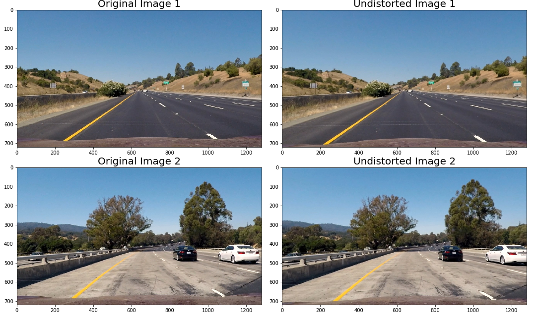
From the above lane lines images, it might be slightly difficult to see the camera distortion change, but if we look at the hood of the car or the cars in the adjacent lanes you can see that the image indeed did become undistorted.
Detecting Lane Lines
Now that we have undistorted images, we can start to detect lane lines in the images. Ultimately, we would like to calculate the curvature of the lanes so that we can decide how to steer our car.
In this section, we use different color spaces, gradient, and direction thresholding techniques to extract lane lines. First of all, we can use different edge detection types of filter (similar to canny edge detection) such as the Sobel filter.
Sobel Filter Thresholding
The sobel filter takes the derivative in the x or y direction to highlight pixels where there is a large change in the pixel values.
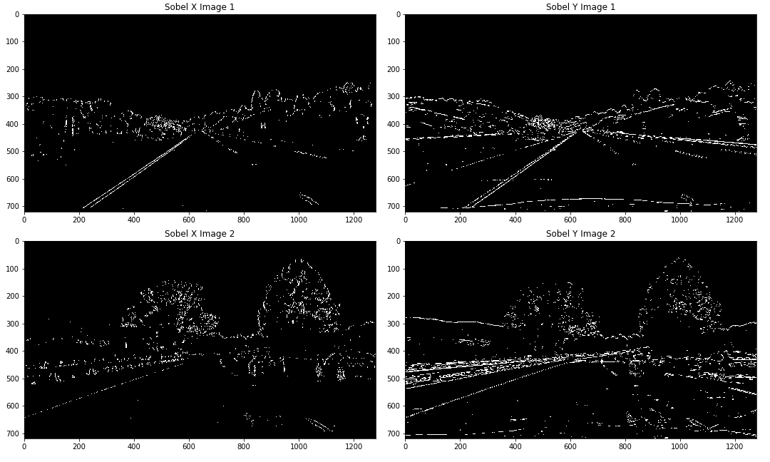
It seems like the x-axis definitely performs better for this task. It makes sense because the lane lines are typically vertical lines and the x-axis direction of the sobel filter highlights vertical lines (versus the y-axis direction highlights many of the horizontal elements of the image).
While in the example above the lane lines are pretty clearly identified, if we look at a harder example the result is not as clean.
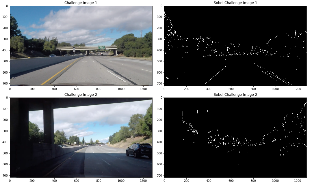
Note that in the top example, we almost completely do not see the yellow lane line. Rather we capture the different colored pavement. In the bottom example, we also mainly capture the different pavement transition.
We can use other thresholding techniques (using color spaces) to identify the lane line even in situations where the we have anomalous aspects in the input image.
Magnitude and Direction of Gradient Thresholding
One approach to potentially clean up the basic sobel filter thresholding is to use the magnitude of the x and y gradients to filter out gradients that are below a certain threshold. We can combine this with the sobel filter above to hopefully achieve better results.
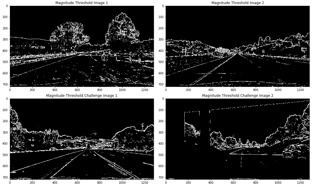
It seems like the magnitude threshold does a fairly good job but is quite similar to the sobel filter alone. Another thresholding technique we can consider is to use the direction of the gradient. In particular because we are looking for lane lines, we know that typically the lane line is a sloped line from the perspective of the onboard camera.
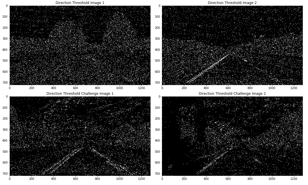
Although now the direction mask seems to capture different aspects than the magnitude of the gradient or the sobel filter, there is a lot of noise in the direction mask. In the end, I ended up not using this mask because it was difficult to incorporate and did not add much value.
Next, we can consider combining the different masks into one function and take a look at the output.
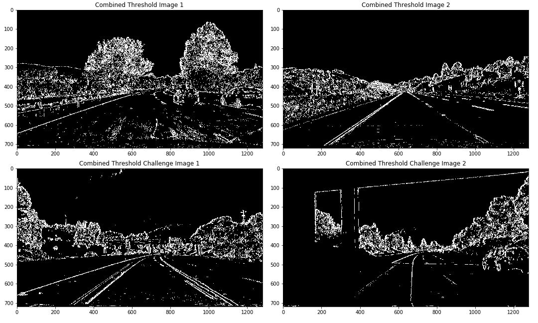
Taking a look at the above output, it seems like the combined thresholding does relatively well on the simple examples, but there are still difficulties with the challenge images. Note that the noise in the rest of the image will be masked away later so we can just aim to better highlight the lane lines using color thresholding.
Color Thresholding

Using the color selection technique (both the HSV and the HSL color spaces) it seems like the thresholding on color now works fairly well! We can see that the lane lines are correctly identified even in the challenge images.
Note that while there is a lot of noise at the top of the images, these portions will be masked out. Now we can try and combine the different thresholding techniques.
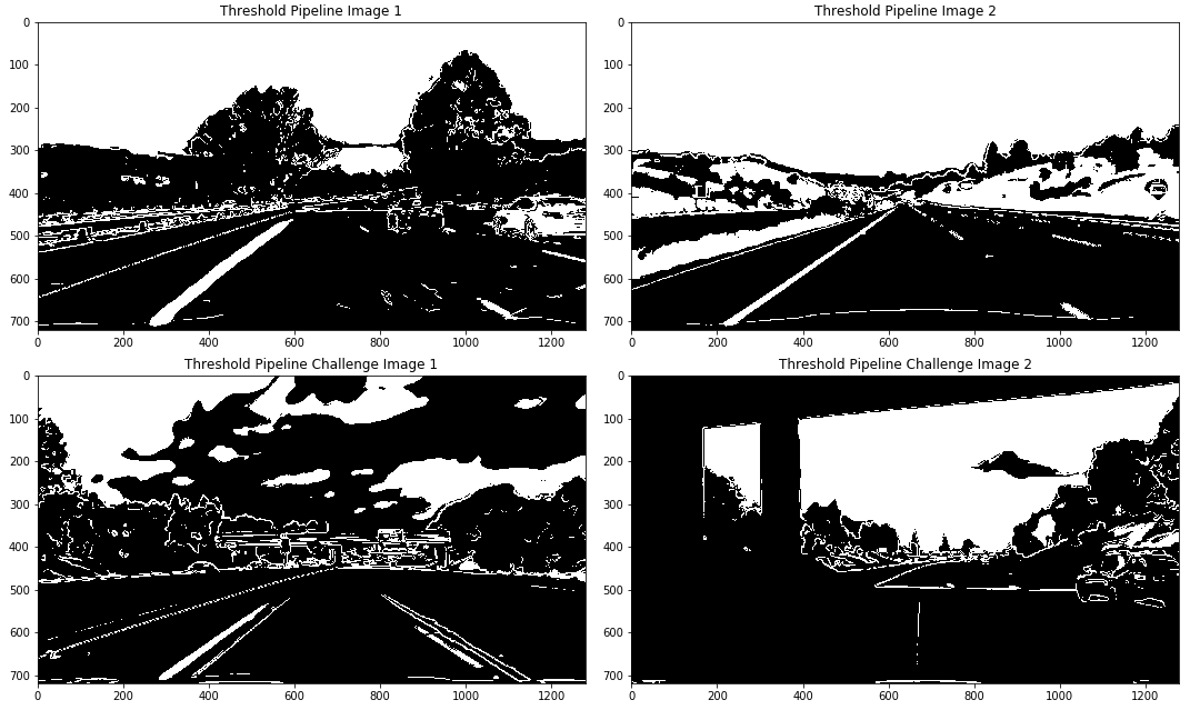
Not too bad! There is a lot of noise that is introduced because of the non-color thresholding. In the end, I decided to use only the color thresholding because it returned the best lane lines.
Perspective Transform
Now we can think about how to adjust the perspective of the image so that we can detect the curvature of the lane lines. One way of doing this is to take a birds eye view of the picture (from the top down). In order to do this, we can use the getPerspectiveTransform and warpPerspective functions in OpenCV.
By transforming the image, we are able to just focus on the part of the picture that is important to the task of finding the lane lines. In the first example below, I used the entire thresholding pipeline. If we compare this to just using the color thresholding pipeline we see that the color thresholding pipeline performs better. The remainder of this project uses the color thresholding.
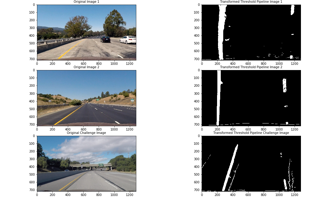
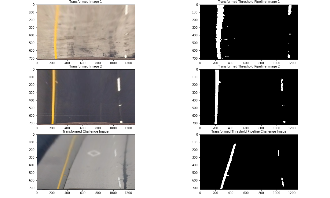
The second of the two above images shows the transformed view before and after thresholding. In order to perform the transformation, we defined source and destination points in the original image and a hypothetical output image onto which the source points are mapped. In this case, 4 points corresponding to the lane lines might be transformed to a square or rectangle shape in the output image, which then returns the lane lines in a straight image if the lane lines are indeed straight.
Sliding Window Search and Polynomial Line Fitting
Next we can try to figure out where the lane lines are and how much curvature are in the lane lines. In order to find the lane lines, we can create a histogram with the columns of the image intensities summed together. This would return higher values for areas where there are higher intensities (lane lines).
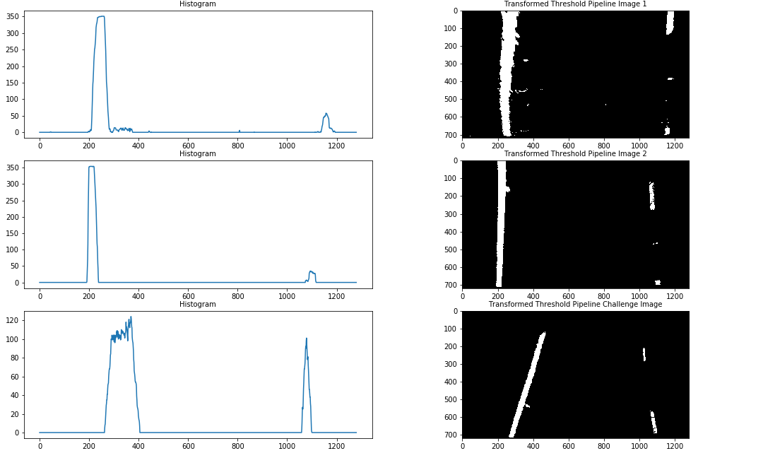
The histogram technique worked fairly well but if we take a closer look we the lane lines (unless they are perfectly straight) will be diagonal across the image. Therefore, it would be best to take a window approach to look at segments of the image (or horizontal bands) in order to be able to capture the curvature of the lanes.
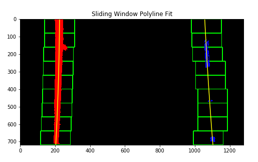
In the above example, we can see that the lane lines are quite well defined and the fitted line is also quite accurate. With the poly lines drawn on the images, we can fill in the area of the image where the lane is most likely to be.
Lane Area and Curve Details

There are also some statistics regarding the curvature of the left and right lanes read more here. The distance from the center of the lane is an approximate calculated using the poly fit lines extended to the bottom of the image as the width of the lane lines and the actual middle of the image as the middle of the car's onboard camera.
Below are links to the final videos:
The challenge video shows some of the shortcomings of the current pipeline. While it works fairly well, there are still some unexpected inputs (previous lane line markings, shadows, and varying pavement colors) that cause the pipeline to make a few mistakes.
Discussion
Overall, this project was really interesting because it was a great extension to the first lane finding project that I worked on. However, I got to use more advanced techniques to solve the same problem. Although the project was interesting, it was also quite difficult and time consuming. Below I will discuss some of the difficulties of the project and also some of the places where the pipeline might fail.
- Detecting and Removing Outliers - in order to build a robust pipeline it is important to take into account the anomalies that might surface in an onboard camera feed. In a few cases there were areas of the road that was obstructed by shadows or different colored pavements. It was important to account for these anomalies by building a function that takes into account the past lane curves and averages to find the "best" fit. This helped to smooth the resulting video of the detected lane lines. Another related difficulty was figuring out what the thresholds should be for the sanity check. The sanity check function would compare the newly calculated curves with the old curves to see if frame by frame there was a large difference in the detected lanes. However, it required a lot of manual fine tuning to get reasonable thresholds for the rejection of certain fitted curves.
- Thresholding - A lot of the time was spent refining the thresholding functions. For the most part, the color thresholding performed the best, but it took a lot of trial and error to correctly select the colors from the different color channels. One important observation was that it is helpful to use different color spaces for retrieving different color lane lines.
- Unexpected Inputs - While the pipeline performs quite well on the videos given, it might not perform well on videos that have a lot of unseen elements, such as large curves and bends, uneven lighting, or lane changing situations. Ideally a self-driving car would take these into account.
Next Steps and Conclusion
The project was extremely rewarding and moving forward there are a lot of improvements that can be implemented. For example, there might be more opportunities to use machine learning to learn how to demarcate the lane lines rather than just use computer vision techniques to extract the lane lines. The difficulty with just using image processing techniques is that there might be situations that are unaccounted for (although if we have no training data a machine learning algorithm would not perform much better).
I am excited to continue researching and learning about this space. There are also very interesting feature extraction techniques that I would like to explore to better be able to detect lane lines. The next step is to think about how these identified lanes can be used to control the vehicle (though there might, in reality, be a few steps before we get there).